Hi, today I want to show you about my project using IC NE555. MY project is 5 second delayed LED light. In this project I using the NE555 as an timer IC. But before we go to the next step, in here I want to explain little bit about IC NE555.
What is NE555?
NE555 is one of the most common chip that used in timer circuits. IC NE55 is an 8-pin chip with 2 inputs and an output. So basically IC NE555 can be used in lot of circuits. n most cases you add a capacitor and resistor to produce a circuit known as a TIME DELAY CIRCUIT and the chip has a detection-pin and an amplifier (also called a power amplifier) to product an output.

Here is picture of IC NE555. Its got 8 pin/ dip that have their own function.
Pin 1 (Ground):
Connects to the 0v power supply.
Pin 2 (Trigger):
Detects 1/3 of rail voltage to make output HIGH. Pin 2 has control over pin 6. If pin 2 is LOW, and pin 6 LOW, output goes and stays HIGH. If pin 6 HIGH, and pin 2 goes LOW, output goes LOW while pin 2 LOW. This pin has a very high impedance (about 10M) and will trigger with about 1uA.
Pin 3 (Output):
(Pins 3 and 7 are “in phase.”) Goes HIGH (about 2v less than rail) and LOW (about 0.5v less than 0v) and will deliver up to 200mA.
Pin 4 (Reset):
Internally connected HIGH via 100k. Must be taken below 0.8v to reset the chip.
Pin 5 (Control):
A voltage applied to this pin will vary the timing of the RC network (quite considerably).
Pin 6 (Threshold):
Detects 2/3 of rail voltage to make output LOW only if pin 2 is HIGH. This pin has a very high impedance (about 10M) and will trigger with about 0.2uA.
Pin 7 (Discharge):
Goes LOW when pin 6 detects 2/3 rail voltage but pin 2 must be HIGH. If pin 2 is HIGH, pin 6 can be HIGH or LOW and pin 7 remains LOW. Goes OPEN (HIGH) and stays HIGH when pin 2 detects 1/3 rail voltage (even as a LOW pulse) when pin 6 is LOW. (Pins 7 and 3 are “in phase.”) Pin 7 is equal to pin 3 but pin 7 does not go high – it goes OPEN. But it goes LOW and will sink about 200mA.
Pin 8 (Supply):
Connects to the positive power supply (Vs). This can be any voltage between 4.5V and 15V DC, but is commonly 5V DC when working with digital ICs.
How does it works?
12v current going through pin 8 and pin 4 to activated the NE555 then the current through resistor and the capacitor. In here capacitor keeps some energy than the current going through to pin 2. From this delayed current we got 500mS current so when the pess button got pressed the LED will light up for 5 second then the LED will off automatically.
Lets make the circuit
After we know about how the NE555 works and how the components will woks with the NE555, it’s time to make our project. But before we make our first prototype of our project, we can test it using Proteus.
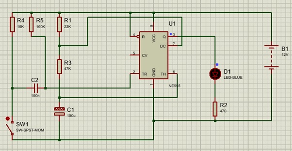
Here is the simulation for this project using ISIS Proteus.

On that picture, when the press button (SW1) didn’t connected, the LED wouldn’t light up.

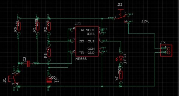
When the press button were pressed the LED will light up for 5 second and automatically off after 5 second. After we testing our schematic project, we can move to designing our PCB’s project. In here I using EAGLE AUTODESK.

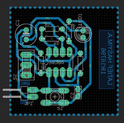
After we make our schematic, we can move to routing our PCB.

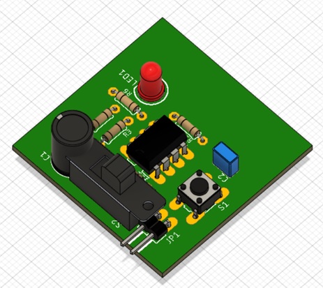
In here, I using 0,8 mm width rout and 0,8 mm drill. We can also check the 3D model of our PCB’s project using AUTODESK Fusion 360.

Here is the list of the components that we will needed
Resistor 100k
Resistor 10k
Resistor 22k
Resistor 47k
Resistor 470 ohm
Capacitor non polarized 100n
Capacitor polarize 100u
Press button
Switch
LED
Battery 12v DC
Designed by Latief Hasyim (19/447077/SV/16796)
