Hello folks, nice to see you again guys!!! Today in this project, we will create Door Bell PCB using IC NE555. This project works by pressing either both of the push buttons or one of them. In this project, we use NE555 as IC. Before that, I will explain the IC NE555.
Now we go on and I will explain what is NE555?
NE555 is one of the most common chips used in the timer circuit. The NE55 IC is an 8-pin chip with 2 inputs and outputs. So basically IC NE555 can be used in many circuits and projects. Most projects are by adding capacitors and resistors to produce a CIRCUIT known as DELAY circuit time and the chip has pin-detection and amplifier (also called Power Amplifier) for output products.
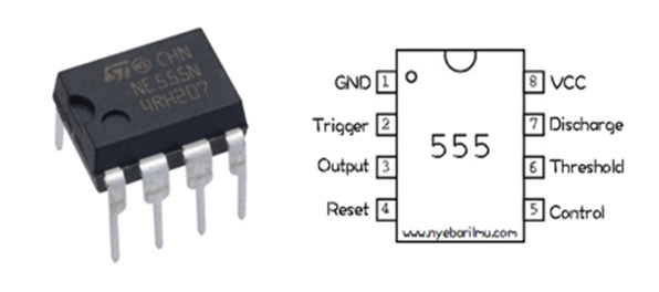
This is a picture of IC NE555. It has 8 pins that have its own functionality.
The Function of The Pin
Pin 1 (Ground/GND)
Connected to Ground/0V.
Pin 2 (Trigger)
PIN 2 has control over pin 6. If PIN 2 is low, and PIN 6 is low, the output runs and remains high. If the PIN 6 is high, and pin 2 goes low, the output goes low while the PIN is 2 low. This PIN has a very high impedance (about 10M) and will trigger around 1uA.
Pin 3 (Output)
This pin has two conditions that are “high” and “Low/Low”.
Pin 4 (Reset)
When pin 4 is connected to the ground, it will be “low”. The IC Output will cause this device to become OFF. Therefore, to ensure IC is in the condition ON, pin 4 is usually given a signal “High”
Pin 5 (Control)
To provide access to the internal voltage divider. By default, the specified voltage is 2/3 VCC.
PIN 6 (Threshold)
Issued to make the Output “Low”. The “Low” condition in this Output will occur when the pin 6 (Threshold) is changed from Low
Pin 7 (Discharge):
At the time of the “Low” Output, pin 7 impedance is “Low”. While the “High” Output, the pin 7 impedance is “High”. This Discharge pin is usually associated with a capacitor that serves as the timing interval determinant. The capacitor will charge and dispose of the payload in line with it.
Pin 8 (VCC)
Connects to a positive power supply (VS). Positive Terminal voltage source DC (approx. 4, 5v or 16v).
How is it Works?
First, it will go through pin 8 and pin 4 to activate NE555 and the current will go through resistors and capacitors. After that pin 6 and 2 are connected on the same track. Pin 3 serves as the output connected directly to the capacitor which will be direct to the speaker as output. While the pin 7 is directly parallel connected to 2 resistors. Pin 1 is directly connected to the ground and pin 5 is not connected because the control occurs on the push button.
Designing The Project
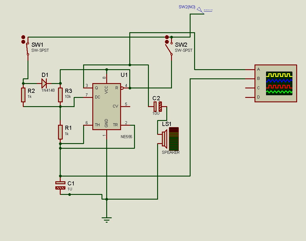
Once we know about how NE555 works and how the component will work with NE555, it’s time to create this project. But before we make our prototype of it, we can test it using Proteus.
Here is a simulation for this project using ISIS Proteus.
Once we’ve tested our simulation project, we can move on to designing our PCB project. In this project, I use Autodesk Eagle as the software.
Schematic:
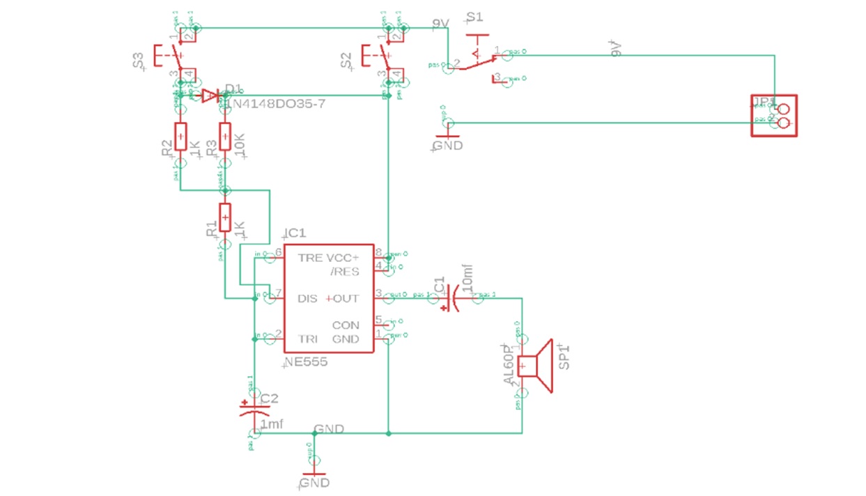
After we make schematic, we can now move to designing PCB route.
Board:
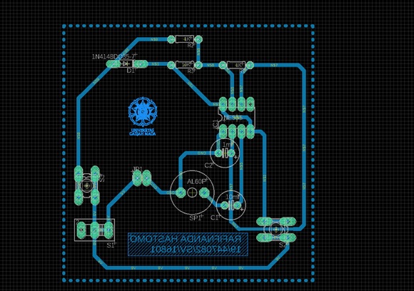
In this board, I use 0,20mm width drill bit. And the size of that board is around 7.5mm x 7.5mm. Why I use so much space? It’s because to anticipating human error when we soldering the components to the board. We usually soldering each other components that are not necessary. Otherwise, it can affect any other elements that usually end up failing its own circuit. So, I use more space to anticipate that kind of problem.
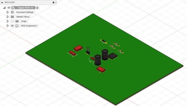
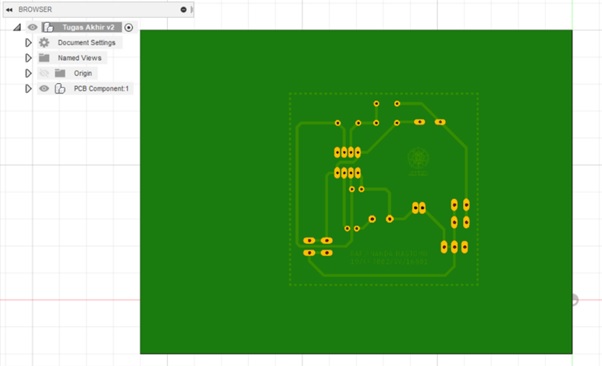
Next, we can also check the 3D model of the PCB project using the 360 Autodesk Fusion.
Top View:

Bottom View:
Here is a list of components we will need
Tools:
- Autodesk Eagle
- Autodesk Fusion
- Drill
- Glossy Paper
- Iron
- ISIS Proteus
- LaserJet Printer
- PC / Laptop
- Pliers
- Solder
- Tin
Components:
- Battery 9V / DC Power Supply 9V
- Capacitor 10uF
- Capacitor 1uF
- Copper Board
- Diode 1N4148
- Ferric Chloride (FeCl3)
- Hydrogen Chloride (HCl)
- IC NE555
- Jumper
- Pinheader
- Push Button (x2)
- Resistor 10K
- Resistor 1K (x2)
- Speaker 8 Ohm
- Switch
- Water (H2O)
- Wire
Making The PCB
Actually, there are many methods to print PCB, but the simplest way is to iron it. With this method, we have a glossy paper iron that has been printed on the PCB board design, and then the design will be attached to the PCB board. Then the copper will be covered and become a PCB path.
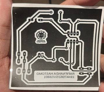
PCB design printed on glossy paper:
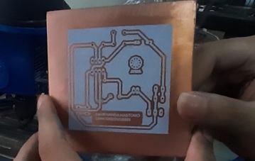
After ironing process:
Afterwards, we will dissolve the circuit with hydrogen chloride (HCl), ferric chloride (FeCl3) and water (H2O) with a 1:2:3 ratio. Once the chemical process is completed around three minutes, the PCB is must be cleaned with water so that the PCB path can be seen after a few minutes dried.
After dissolution process:
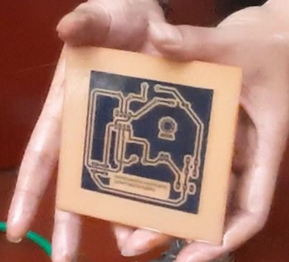
Next is the drilling process. Here we are using 0.20 mm drill bit size. I’d like to use bigger drill bit, because it is deliberately made to anticipate mistakes on the drilling itself.

And finally, we place all the components, then we solder it with the tin on the PCB.
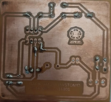
Anddddd, it’s finished hooraayy!!!
So that’s my short article about making the DoorBell Circuit using IC NE555. Hopefully, the science that I write here can be a general reference for all of you. Thanks again to all of you readers also everyone who has supported me in this project. See yaa folks!!!!
Designed by Rafifnanda Hastomo (19/447082/SV/16801)