
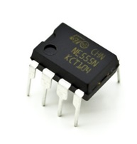
Machine Gun Sound Circuit is a simple electronic circuit that will make a sound like a Machine Gun using IC 555 as a timer. Here I am going to explain how to make the circuit and also how the circuit works. First of all, before we get to know the circuit, we have to know the most important component fro the circuit itself. Yes, the IC Timer 555. IC 555 is one of the most popular and widely use ICs of all time. The 555 timer designed by Hans Camenzind in 1971 can be found in many electronic devices from the simple on to the complex one. It is a highly stable integrated circuit that can produce accurate time delays and oscillations. This is the picture of IC 555. IC 555 has 8 pins and each of them has its functionality.
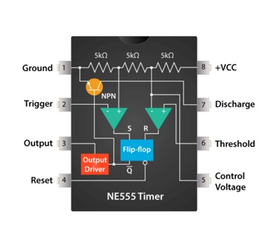
What’s the function of each pin?
- Ground : Ground reference voltage 0V.
- Trigger : The Output pin goes high and a timing interval starts when this input falls below 1/2 of CTRL voltage (which is typically 1/3 Vcc, CTRL being 2/3 Vcc by default if CTRL is left open). In other words, Out is high as long as the trigger low. Output of the timer totally depends upon the amplitude of the external trigger voltage applied to this pin.
- Output : This output is driven to approximately 1.7 V below +Vcc, or to GND.
- Reset : A timing interval may be reset by driving this input to GND, but the timing does not begin again until RESET rises above approximately 0.7 volts. Overrides TRIG which overrides threshold.
- Control : Provides “control” access to the internal voltage divider (by default, 2/3 Vcc).
- Threshold : The timing (OUT high) interval ends when the voltage at threshold is greater than that at CTRL (2/3 Vcc if CTRL is open).
- Discharge : Open collector output which may discharge a capacitor between intervals. In phase with output.
- Vcc : Positive supply voltage, which is usually between 3 and 15 V depending on the variation.
So, after we got to know what is IC 555 and how this thing works, we are moving on to the next step, the making of Machine Gun Sound Circuit Design.
Step 1 : Schematic and Board with Autodesk Eagle.
So the first step is making the schematic design of the circuit.
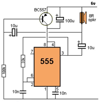
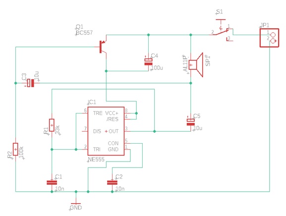
This is the schematic of Machine Gun Circuit that has been created.

After we had made the schematic, we switch to Board. The size of the board I had made is 5cm x 5cm. The route and the pads I used is large to prevent mistakes when we are soldering the components to the PCB. This could cause the failing of the circuit and we have to try again.
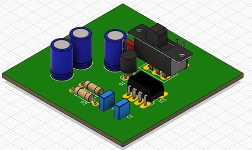
Step 2 : 3D Model PCB in Autodesk Fusion360.
We are using Autodesk Fusion360 to convert the board into 3D model, so we get to know how it is gonna be in real situation.
Step 3 : Run the simulation using ISIS Proteus.
Running a simulation is simply enough just to make sure we understand how the circuit works in a real situation.

This is how it looks in ISIS Proteus when we are running the simulation. The sound is actually come out but this is just a picture, so there is no sound unfortunately.
Making The PCB
There are a lot of methods to create the PCB and we are going to choose the Iron Method.
First, prepare the tools and components.
Tools :
- Printed Circuit Board on Glossy Paper
- Iron
- Drill
- Pliers
- Solder
- Tin
Components :
- One 555 IC
- One BC557 Transistor
- One 8ohm Speaker
- Two 10nF Ceramic Capacitors
- One 100uF Electrolytic Capacitor
- Two 10uf Electrolytic Capacitor
- One 100K resistor
- One 33K resistor
- One 6-12v power supply
- Speaker 8 Ohm
Step 1 : The Ironing Process
This process requires the PCB design that already printed on glossy paper, PCB board and iron. The process is at least 20 minutes to completed. Put the glossy paper above PCB board with the printed design side facing the board.
Step 2 : The Etching Process
This process is about to dissolve the unused copper with HCl and FeCl3 sufficiently.
Step 3 : The Drilling Process
This process is about to make a hole, which will be used to put the component pin. Be careful with drill, it’s too dangerous.
Step 4 : The Soldering Process
We are at the last step of making the machine gun sound circuit with IC 555 Timer. This process is about to put all the components on the PCB board. This process are more dangerous than the drill process so you guys have to be more careful.
Designed by Muhammad Aulia Alfarisi (19/441162/SV/16514)
Your MACHINE Gun sound circuit is of interest to me as I wish to make this circuit to operate at a higher
frequency in order to drive away monkeys without disturbing the neighborhood. I would like it to operate at 17 Khz. ~ 25 Khz. Could you kindly give me the component details for this change.
Awaiting a favourable reply.
Best Regards,
Ronald Fonseka,
SRI LANKA
Dear Sir,
Could you please let me know how I could change the above circuit to obtain
Machine Gun Sound at a frequency of 15Khz ~ 25 Khz. to drive away monkeys
without disturbing the neighborhood.
Best Regards,
Ronald,
SRI LANKA
Email: ronaldfonseka@yahoo.com