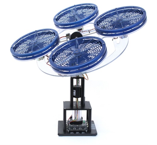
Hello friends! In this article, we will share about 3 DOF Hover and how to design it using Solidworks Software. Happy Reading fella!
The 3 DOF Hover consists of a planar round frame with four propellers. The frame is mounted on three degrees of freedom pivot joint that enables the body to rotate about the roll, pitch and yaw axes. The propellers are driven by four DC motors that are mounted at the vertices of the frame. The propellers generate a lift force that can be used to directly control the pitch and roll angles. The total torque generated by the propeller motors causes the body to move about the yaw axis. Two of the propellers are counter-rotating so that the total torque in the system is balanced when the thrust of the four propellers is approximately equal. The voltage signals going to the motors, as well as the pitch and yaw encoder signals, are transmitted through a slip ring. The slip ring removes the need for wires and allows for 360 degrees free motion about the yaw axis. Furthermore, it reduces the amount of friction and loading about the moving axis.
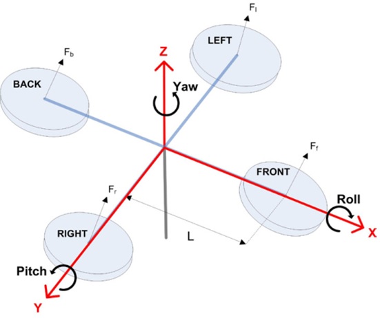
After knowing a little about 3 DOF Hover lets try to make the design.
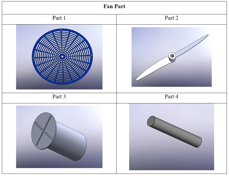
The First Step: The first thing that we have to do is make each part of the 3 DOF Hover or you can use our part from the from our member grabcad’s account by click on this link below:
https://grabcad.com/library/3-dof-hover-1
The following are the pictures of the part we have made:
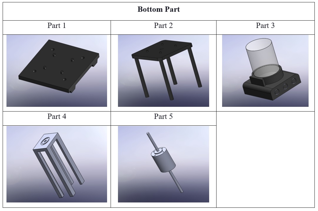
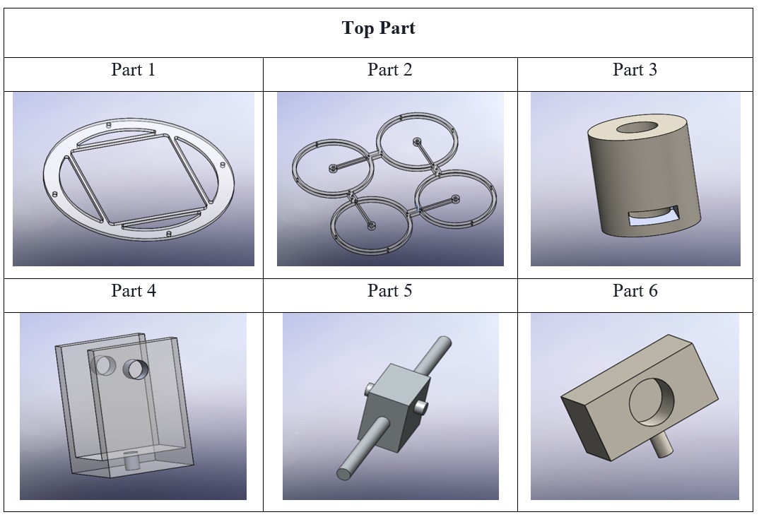
The Second Step:
The second thing that we have to do is assemble each part that you have until it becomes a 3 DOF hover. Here the picture of 3 DOF Hover after we finished the assembly step. I also post a tutorial video of the 3 DOF Hover on Youtube. Link for the video is the following.

Thank you for reading.
Designed by:
- Muffida Kurnalia Yovika Putri (19/447079/SV16798)
- Alam Ega Kumara (19/447071/SV/16790)
- Nabilla Destrianty (19/447292/SV/16986)
