
Helloo Assalamau’alikum Wr. Wb. I want to show you about my project about Design 3D Computer Aided Drawing. My project is make a 3D Design of Quadrotor . In this project I using Solidworks 2020 App. But before we go to the next step, in here I want to explain little bit about Quadrotor and Solidworks.
What’s Quadrotor?
In the world today there is a widespread use of drones that refer to rotor, multi rotor or single aircraft that can be controlled remotely. Drones are available in various sizes and rotor configurations, depending on what is needed and functioned from the mini-quadcopters that can be easily controlled by users to FPV Racing drones that can fly at high speed. Quadcopter or can be called Quadrotor is an Unmanned Aerial Vehicle (UAV) air explorer robot which belongs to the micro UAV category and is widely used by several institutions or agencies. Quadcopter robot is a UAV that has a special characteristic that is easily recognized, which has four motor propellers that are used as its driving force. Quadrotor is one type of rotorcraft that has 4 rotors as a propeller drive that produces lift n this quadrotor has a era to take a picture or video. Quadrotor can vertical take off and landing. Vertical Take Off Landing (VTOL) Aircraft is a type of aircraft that can take off and landing perpendicular to the earth so that it can be done in a narrow place. Helicopters, tricopters, quadcopter, and similar multi-motors fall into this category. By changing the magnitude of the rotation speed of the four motors then quadcopter can move up, down, forward, backward, left, right and rotation. The above movement is better known as pitch (moving forward or backward), roll (move left or right), and yaw (left rotation or right rotation).
In this article we will discuss about making 3D Quadcopter animations using the Solidworks application. Before knowing the design of the 3D Quadcopter design it would be better if you first know the application of solidworks that will be used to make sketches from 2D to 3D modeling Quadcopter. Solidworks is one of the CAD software made by Dassault Systems used to design machining parts or arrangement of machining parts in the form of assembling with 3D display to represent parts before the real part is made or 2D display (drawing) to draw the machining process. At a glance we already know the definition of the solidworks application. Next we have to plan what steps are needed to make a quadcopter design to simulate it.
OK, Now I want to show part of Quadrotor
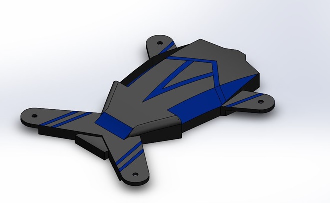
- Upper Body, as a cover for the quadrotor top This part is a thick cover with various designs that prioritize aesthetics, but still in accordance with the main function.
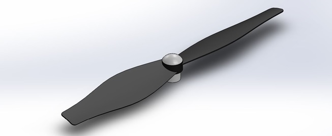
- Propeller, is a tool to run an aircraft. This propeller transfers power by converting rotational motion be the driving force to drive a vehicle like an airplane fly, to go through a mass like air, by rotating two or more twin blades of a main shaft. A propeller acts as a wing spin, and produce a force that applies the Bernoulli principle and Newton’s laws of motion produce a difference in pressure between surfaces front and back.
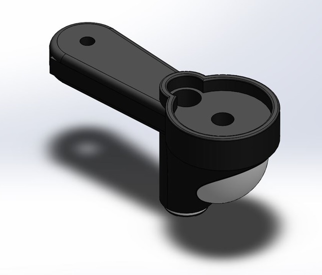
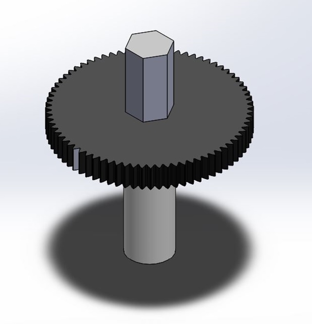
- Handle, the handle is the place for the rotor and the main shaft for all parts.
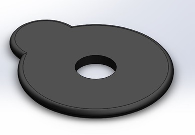
- Cover Handle, this part is used to close the handle.
- Gear, is the gears of a rotating machine that functions to transmit or transfer power used for propulsion.
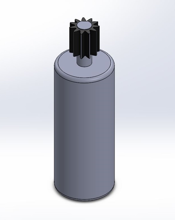
- Motor Gear, each propeller is connected to the motor through a reduction gear that is a gear that reduces and increases the speed of the input rotation at the output that works according to the ESC (Engine Speed Control) command.
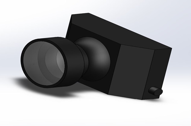
- Camera, the use of (digital) eras in the robotics world is known as robotics vision. Like the eye in humans, a era can be designed as an eye on robots. With the eye, robots can more freely “see” their environmentas humans. In the last two decades robotics vision technology has developed very fast. This progress was achieved thanks to the development of IC chip technology more compact and fast, and progress in the field of computers (as a processor), both hardware and software. Optical technology on basically still using techniques that have evolved since more than 100 years ago, namely the use of convex and concave lens configurations. The ability of a digital era is usually measured by the resolution of the image capture in pixel / inch or pixel / cm. The greater the resolution, the more accurate the captured image.
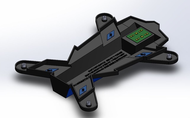
- Lower Body, bottom cover of quadrotor. Which holds a variety of electronic parts such as Arduino, batteries, Engine Speed Control, and other components.
Designed by:
- Muhammad Fathur Rizqi Alfathir (19/447078/SV/16797)
- Ervinta Aprilliana (19/447076/SV/16795)
- Aditya Putra Yudhananta (19/447069/SV/16788)