• Tentang UGM
  • PIKA UGM
  • Sekolah Vokasi
  • Departemen TEDI
  • Fahmizal Blog
Universitas Gadjah Mada Menara Ilmu Otomasi
Departemen Teknik Elektro dan Informatika
Sekolah Vokasi Universitas Gadjah Mada
  • Beranda
  • Penelitian
    • Control and Automation System
    • Internet of Things (IoT)
    • Deep Learning
    • Robotics
      • Humanoid Robot
      • Self-driving Car Robot
      • Mobile Robot
      • Arm Manipulator Robot
      • Unmanned Aerial Robot
      • Underwater Robot
    • Covid-19
      • Face Shield
      • Ventilator
      • UVD Mobile Robot
      • UVC Box Sterilizer
    • Capstone Project
    • Publikasi
  • Berita
  • Artikel
  • Buku
  • Video
  • Tentang
    • Tim Menara Ilmu
    • Makna Logo
    • Kontak
  • Beranda
  • CAD Design
  • CAD Design
Arsip:

CAD Design

Ball and Beam CAD Design

Artikel Friday, 10 January 2020

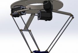
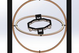
Ball and Beam System adalah sebuah sistem yang terdiri dari sebuah bidang segi empat (beam) dan sebuah bola (ball). Pada dasarnya, Ball and Beam System ini mengedepankan system yang stabil dan seimbang. Pada Ball and Beam terdapat bola yang dapat bergerak bebas dan posisi dari perpindahan bola tersebut dapat diatur sesuai dengan yang diinginkan. Pergerakan bola pada Ball and Beam System dipengaruhi oleh besarnya gaya yang ditimbulkan oleh kemiringan batang tempat bola berada, dimana untuk memiringkan batang digunakan motor yang akan menggerakkan batang tersebut sesuai dengan posisi bola. Karena membutuhkan system yang stabil dan seimbang maka komposisi desain harus proporsional. Dalam mendesain Ball and Beam System ini digunakan software Solidworks. Pada pembuatan desain CAD ini kami mebuatnya dengan referensi dari Youtube dengan judul “PID Control of a Ball and Beam System”.

Sumber : https://www.youtube.com/watch?v=0OcFkrz9nyY

  • Desain mekanik

Pada projek ini, kami menggunakan software Solidworks. Dimulai dari pembuatan desain bagian alas atau base terlebih dahulu kemudian dibuat bagian tiang penyangganya pada kedua sisi. Selanjutnya, membuat desain batang besi yang akan digunakan untuk dilewati oleh bola. Dibuat juga besi pipih sebagai engsel dan membuat sambungan antara tiang penyangga dan batang besi. Pada desain Ball and Beam System digunakan sebuah micro trafo yang dapat kita dapatkan dari GrabCad.

  • Assembly

Setelah semua bagian desain yang telah dibuat tadi selesai dibuat, semua bagian tadi di sambung dengan menggunakan fitur assembly pada software Autodesk Inventor sehingga didapatkan hasil desain menyerupai bentuk pada referensi.

Disusun oleh:

  1. Latief Hasyim A    (19/447007/SV/16796)
  2. Zubainindra Bagus F M (19/447084/SV/16803)
  3. Nur Nayla Rahma     (19/447293/SV/16987)

Motorized Camera Slider CAD Design

Artikel Friday, 10 January 2020

Camera Slider adalah tempat dimana kamera DSLR, webcam, atau kamera broadcast diletakkan dan digeserkan menggunakan manual baik ke kiri-kanan atau ke depan-belakang sesuai dengan jenis slider. Fungsi utama dari Camera Slider ini adalah untuk memperhalus movement kamera, baik dari segi teknik pengambilan maupun segi sinematografi. Slider merupakan alat pendukung kamera untuk memberikan camera movement yang berjalan pada rel.

Motorized Camera Slider digerakkan oleh sebuah motor penggerak. Motorized Camera Slider adalah konsistensi movement sangatlah stabil karena operator hanya mengoperasikan lewat aplikasi di ponsel. Operator hanya mengatur pergerakannya, nantinya Stepper Motor pada slider akan bergerak sesuai perintah operator yang telah disetel pada aplikasi. Panjang track atau rel beragam, antara 20 sentimeter hingga 90 sentimeter. Motorized Camera Slider memiliki kekurangan yaitu bergantung pada baterai dan harga yang relatif tinggi. Pembuatan Motorized Camera Slider dilakukan dengan menggunakan aplikasi Solidworks. Dimana aplikasi Solidworks merupakan salah satu CAD software yang digunakan untuk merancang part permesinan yang berupa tampilan 3D (assembly) atau tampilan 2D (drawing).

Bagian beserta Fungsi pembuatan Motorized Camera Slider:

Desain CAD menggunakan Solidworks

  • Frame, berfungsi sebagai tempat Camera Stand yang dapat digeserkan baik ke kiri-kanan atau ke depan-belakang.

  • Camera Stand, berfungsi sebagai tempat utama camera diletakkan.

  • Pulley, berfungsi sebagai alat penggerak dari Motorized Camera Slider.

Prinsip Kerja dari Motorized Camera Slider

Motorized Camera Slider digerakkan oleh sebuah motor penggerak. Motorized Camera Slider adalah konsistensi movement yang stabil karena operator hanya mengoperasikan lewat aplikasi di ponsel. Apabila Stepper Motor dihidupkan maka rantai akan berputar dan bergerak menuju bracket. Bracket akan bergerak maka dudukan kamera (base) akan bergerak juga sesuai perintah yang diberikan lewat aplikasi yang berada di ponsel.

Disusun oleh:

  1. Naufal Rashad Aryaputra (19/447081/SV/16800)
  2. Fifi Novira Belinda (19/441157/SV/16509)
  3. Silpana Cristati Hutauruk (19/441166/SV/16518)

Delta Robot CAD Design

Artikel Friday, 10 January 2020

“Robot delta adalah jenis robot paralel yang terdiri dari tiga lengan yang terhubung ke sambungan universal di pangkalan. Fitur desain utama adalah penggunaan jajaran genjang di lengan, yang mempertahankan orientasi efektor akhir, berbeda dengan platform Stewart yang dapat mengubah orientasi efektor ujungnya.”

Dikutip dari https://en.wikipedia.org/wiki/Delta_robot

Delta robot yang merupakan robot 3 lengan dengan prinsip keseimbangan memilliki banyak peran dalam bidang otomasi, utamanya otomasi industri. Robot delta memiliki bagian – bagian berupa substrat, penutup, motor, poros utama, rekayasa / manipulator lengan, gripper, dan lain – lainnya ini memiliki peran sebagai robot pengemas, robot penyortir, pengemasan material, dan bahkan pengelas.

Prinsip kerja dari robot delta ini didasari oleh fuzzy function logic, dan juga perhitungan besarnya sudut bebas untuk dasar gerakan lengan. Robot delta, sejatinya juga dilengkapi dengan sensor visi dan sensor ultrasonik mendapatkan perintahnya dengan alur menerima visi melalui kamera / sensor visi, yang kemudian akan memperhitungkan posisi dan koordinat dari objek yang akan diberi perintah. Robot delta memiliki tingkat akurasi tinggi karena dilengkapi dengan fungsi logika fuzzy dan juga berbagai macam sensor yang cukup peka pula.

Link grabcad:
https://grabcad.com/library/delta-robot-15

Disusun oleh:

  1. Wening Nur Suminar (19/441169/SV/16521)
  2. Aftzar Arrahman (19/447285/SV/16979)
  3. Elisabet Gusti Tristiati (19/441156/SV/16508)


Ornithopter CAD Design

Artikel Friday, 10 January 2020

Bentuk dasar dari pesawat adalah tiruan dari bentuk rangka burung. Sedangkan burung terbang menggunakan kepakan kedua sayapnya tanpa menggunakan turbin atau propeler. Seluruh anatomi tubuh burung merupakan awal terbentuknya berbagai macam pesawat. Dimulai dari pesawat yang berteknologi rendah hingga berteknologi canggih sekalipun. Namun, hampir tidak ada yang memiliki mekanisme terbang seperti burung. Hal tersebut merupakan kesempatan bagi bidang robotik untuk menambah ranah ilmunya dengan menciptakan ornithopter sebagai robot burung yang nantinya dapat dimanfaatkan sebagai alat dalam bidang intelijen, entertainment, militer, geofisika, dan sebagainya.

Ornithopter sendiri berasal dari Bahasa Yunani, yaitu ornithos = burung dan pteron = sayap. Namun ornithopter dapat diartikan sebagai ‘mesin terbang yang menggunakan prinsip terbang seperti burung.’ Cara kerjanya adalah dengan meniru gerakan burung ketika terbang dengan mengepakan sayapnya, sehingga dapat mengangkat seluruh tubuh burung ke udara. Cara kerja Bird Ornithopter ini menggunakan motor DC brushless dan ESC sama seperti pesawat RC. Alih-alih menggunakan propeller untuk terbang, gerak kepakan sayap dihasilkan dari putaran gear yang terhubung dengan kerangka sayap. Sedangkan ekor berfungsi sebagai kontrol arah terbangnya.

Selanjutnya, pembuatan ornithopter dapat dilakukan menggunakan aplikasi Solidworks. Solidworks merupakan perangkat lunak untuk membantu proses desain suatu benda atau bangunan dengan mudah. Keunggulan Solidworks dari software CAD lain adalah mampu menyediakan sketsa 2D yang dapat diupgrade menjadi bentuk 3D. Selain itu pemakaiannya pun mudah karena memang dirancang khusus untuk mendesain benda sederhana maupun yang rumit sekali pun.

Berikut adalah tahapan pembuatan Ornithopter:

  • Desain CAD menggunakan Solidworks

Pembuatan ornithopter dapat didesain menggunakan aplikasi Solidworks. Untuk membuat ornithopter, desain dibagi menjadi beberapa part, yaitu: body, sayap, ekor, baterai Lipo, gear, motor DC brushless, arduino, receiver, regulator, kepala, ESC, adapter, saklar dan pin. Bagian yang digambar terlebih dahulu adalah body kemudian kerangka sayap dan komponen mesin penggeraknya.

  • Assembly Part CAD menggunakan Solidworks

Setelah menggambar seluruh bagiannya, ornithopter dibangun dengan menyatukan body dengan sayap dan komponen penggeraknya. Digunakan pin untuk menghubungkan antar komponen.

  • Simulasi Gerak menggunakan Solidworks

Simulasi desain ornithopter dengan Solidworks dapat dilakukan dengan toolbar ‘Simulation’ untuk menggerakkan gear dan sayap. Hasil desain bird ornithopter kami dapat diakses di situs grabcad.com dengan link https://grabcad.com/library/bird-ornithopter-1

Disusun oleh:

  1. Andi Baihaky (19/441150/SV/16502)
  2. Tasya Amelia Putri (19/441168/SV/16520)
  3. Michael Khrisna Setiadharma (19/447291/SV/16985)

Test Bench Gimbals Rig for Quadcopter CAD Design

Artikel Friday, 10 January 2020

Here we will build a Test Bench Gimbals Rig for Quadcopter. but first, we need to know first what is a Test Bench Gimbals Rig for Quadcopter?

Quadcopter is a helicopter that lifted and driven by 4 rotors. The rotor is an electric motor or an electric generator that rotates on the Rotor axis. Rotor rotation is caused due to the magnetic field and email wire coil on the rotor. Quadcopters are classified as rotor craft, as opposed to planes since their lift is produced by a set of rotors. A French aircraft designer and manufacturer named Louis Charles Breguet was the first designer of the quadcopter.

To find out if the quadcopter can be used properly, it requires tested on the bench gimbals rig first. This test bench is used to test whether the quadcopter is viable to operate or not. Most gimbals test bench is a circle shaped, but here we will make it with a square shape as its gyroscope frame.

Since the rapid growing era of technology around the year 2005 to 2010, advances in electronics allowed the production of light flight controllers. This resulted in quadcopter configurations becoming so popular for small unmanned aerial vehicles (UAV). With its small size and maneuverability, the quadcopter can be flown indoors or outdoors. The design that is almost similar to a drone causes this object to be often called a drone. Although like that, both the quadcopter and the drone have a difference in many aspects: Drone is a generic term used for all unmanned aerial vehicles (UAV), although quadcopter can also fly unmanned by combining the character of a drone inside. Drone is a generic term used for all unmanned aerial vehicles (UAV), although quadcopter can also fly unmanned by combining the character of a drone inside. Unmanned aircraft could be described as drones or quadcopters (depending on their characteristics), but the aircraft could not be classified as a quadcopter from its characteristics.

  • Drone is a generic term used for all unmanned aerial vehicles (UAV), although quadcopter can also fly unmanned by combining the character of a drone inside. Unmanned aircraft could be described as drones or quadcopters (depending on their characteristics), but the aircraft could not be classified as a quadcopter from its characteristics.
  • Between both of them, drones usually have a GPS set to move from one place to another without a crew, unlike the quadcopter in general that is controlled through a remote.
  • Unmanned planes have the ability to actually fly by themselves with the help of GPS, but some manufacturer also made quadcopter that with built-in GPS inside it to be able to fly independently

The following model is an overview of the quadcopter that is designed from SolidWorks software. SolidWorks is one of the CAD programs used to help to design the process of an object or building with ease. CAD (Computer Aided Design) Program  is a program devoted to creating/design objects in the form of 2 dimensions as well as 3 dimensions.

SolidWorks divided into 3 versions, based on its function and needs.

  1. Solidwork Standard, commonly used to assist 3-dimensional and 2-dimensional modeling process with maximum speed.
  2. SolidWorks Premium, a 3-dimensional CAD software with a comprehensive design and additional features.
  3. Solidworks Professional, higher above Solidworks standard and premium. Solidworks Professional has better features, such as: file management, almost real rendering results, etc.

Compared to other CAD software, SolidWorks occupies the top position of most users as a modeling software. Modeling is creating a 3-dimensional object that is apllied in visual form. The 3-dimensional Modeling was originally used for scientific purposes only. Modeling also has 3 types, namely:

  1. Polygonal Modeling, is a Modeling object that uses dots to become a line to create fields.
  2. Curve Modeling, is a Modeling object that uses curves to create fields.
  3. Digital Sculpting, a modeling object that has a high degree of smoothness, is usually used to design sculptures.

SolidWorks was introduced in 1995 as a competitor to CAD programs such as Pro / ENGINEER, NX Siemens, I-Deas, Unigraphics, Autodesk Inventor, Autodesk AutoCAD dan CATIA.

The design starts from several parts, it includes:

  • Rectangle gyroscope frame
  • Gimbal
  • Spin axis
  • Bolt
  • Gimbal bridge connector
  • Rotor

And then, it will be assembled at the final stage. For more details, it can be found on the following video link.

Test Bench Gimbal Rig for Quadcopter Parts

  • Gyroscope is a device for measuring or maintaining orientation, with the principle of angular momentum determination, this tool works with the accelerometer. The mechanism is a spinning wheel with a disc in it that remains stable. This stuff is often used to be in robots or drones as well as other advanced tools. Inside the gyroscope, there is a gyro sensor to determine the orientation of the motion by resting on the wheels or discs that rotate quickly on the axes. The gyro sensor itself has a function to detect the movement according to Gravity, or in other words, detect the movement of the user

The working principle of Gyroscope

The gyro sensor must be calibrated first with a pendulum. The calibration process serves to obtain the calibration factor value. The gyroscope has the output of angular velocity from the 3-axis direction, which then will be the angle of the Phi (right and left) of the Y-axis and later to be the angle of the theta (top and bottom), therefore the Z-axis later becomes the angle of psi (front and back).

The usability of Gyroscope

  1. In the past, the gyroscope was already used for navigation, camera stabilizer, and aviation.
  2. On Android phones, Gyroscope can provide orientation information with more precision up to 360 degrees angle. Thanks to this particular sensor, the Android photo sphere camera feature can provide information on how many devices that have been rotated and in which direction.
  3. Gyroscope is also applied to games that are mostly on the smartphone either it’s on IOS or android platform, where the use of games for example is a 3D-based game and has ample space, for example, in a game we usually have to swipe the screen in various directions to move the space around, but with the presence of this tool only have to move the gadget in the direction that is desired.

The advantage of Gyroscope

  1. It can detect movement in any direction.
  2. The result of an image from the movement is smoother/not broken as in the accelerometer.
  3. Not influenced by gravity.

The disadvantage of Gyroscope

  1. The price is quite expensive.
  2. It only can be used if there is any
  • The Spin Axis can move to a three-point axle, i.e. with quadcopter drones. The quadcopter can move forward, left to right, and spin or on the X, Y, Z axis or often called Pitch, Roll, Yaw movement. Pitch is a drone movement to move forward and reverse. The move can by advancing the stick forward and backward according to the RC settings we do. Roll is a drone movement for the right or left of the movements that can be reversed to the right and left of the RC. While Yaw is a drone movement to spin from the left or right and its movements are also controlled with the same RC moves with a roll but different sticks.
  • Gimbals are a quadcopter balancing system. also, dreadlocks serve as a liaison between the drones and the camera respective shapes that are different but have the same function that is to create a steady shot of photos or videos using drones. so if there any shocks and winds factor that can make the drone unsteady or the camera blur, it can be eliminated.
  • The rotor is part of an electric motor or electric generator that rotates on the rotor axis. Rotor rotation is caused due to magnetic field and email wire coil on the rotor. Quadcopters are classified as  rotor craft, as opposed to planes.

In this project the Rig for Quadcopter Gimbal made on Solidwork are designed slightly different on the Gyroscope part, the previously shaped Circle replaced to the shape of  the box  according to the video on the link https://www.youtube.com/watch?v=wAxHFTzAP-U

Designed by:

  1. Muhammad Aulia Alfarisi (19/441162/SV/16514)
  2. Rafifnanda Hastomo (19/447082/SV/16801)
  3. Rizky Nur Handayani (19/447083/SV/16802)

Quadrotor CAD Design

Artikel Friday, 10 January 2020

Helloo Assalamau’alikum Wr. Wb. I want to show you about my project about Design 3D Computer Aided Drawing. My project is make a 3D Design of Quadrotor . In this project I using Solidworks 2020 App. But before we go to the next step, in here I want to explain little bit about Quadrotor  and Solidworks.

What’s Quadrotor?

In the world today there is a widespread use of drones that refer to rotor, multi rotor or single aircraft that can be controlled remotely. Drones are available in various sizes and rotor configurations, depending on what is needed and functioned from the mini-quadcopters that can be easily controlled by users to FPV Racing drones that can fly at high speed. Quadcopter or can be called Quadrotor is an Unmanned Aerial Vehicle (UAV) air explorer robot which belongs to the micro UAV category and is widely used by several institutions or agencies. Quadcopter robot is a UAV that has a special characteristic that is easily recognized, which has four motor propellers that are used as its driving force. Quadrotor  is one type of rotorcraft that has 4 rotors as a propeller drive that produces lift n this quadrotor has a era to take a picture or video. Quadrotor  can vertical take off and landing. Vertical Take Off Landing (VTOL) Aircraft is a type of aircraft that can take off and landing perpendicular to the earth so that it can be done in a narrow place. Helicopters, tricopters, quadcopter, and similar multi-motors fall into this category. By changing the magnitude of the rotation speed of the four motors then quadcopter can move up, down, forward, backward, left, right and rotation. The above movement is better known as pitch (moving forward or backward), roll (move left or right), and yaw (left rotation or right rotation).

In this article we will discuss about making 3D Quadcopter animations using the Solidworks application. Before knowing the design of the 3D Quadcopter design it would be better if you first know the application of solidworks that will be used to make sketches from 2D to 3D modeling Quadcopter. Solidworks is one of the CAD software made by Dassault Systems used to design machining parts or arrangement of machining parts in the form of assembling with 3D display to represent parts before the real part is made or 2D display (drawing) to draw the machining process. At a glance we already know the definition of the solidworks application. Next we have to plan what steps are needed to make a quadcopter design to simulate it.

OK, Now I want to show part of Quadrotor

  • Upper Body, as a cover for the quadrotor top This part is a thick cover with various designs that prioritize aesthetics, but still in accordance with the main function.

  • Propeller, is a tool to run an aircraft. This propeller transfers power by converting rotational motion be the driving force to drive a vehicle like an airplane fly, to go through a mass like air, by rotating two or more twin blades of a main shaft. A propeller acts as a wing spin, and produce a force that applies the Bernoulli principle and Newton’s laws of motion produce a difference in pressure between surfaces front and back.

  • Handle, the handle is the place for the rotor and the main shaft for all parts.

  • Cover Handle, this part is used to close the handle.

  • Gear, is the gears of a rotating machine that functions to transmit or transfer power used for propulsion.

  • Motor Gear, each propeller is connected to the motor through a reduction gear that is a gear that reduces and increases the speed of the input rotation at the output that works according to the ESC (Engine Speed ​​Control) command.

  • Camera, the use of (digital) eras in the robotics world is known as robotics vision. Like the eye in humans, a era can be designed as an eye on robots. With the eye, robots can more freely “see” their environmentas humans. In the last two decades robotics vision technology has developed very fast. This progress was achieved thanks to the development of IC chip technology more compact and fast, and progress in the field of computers (as a processor), both hardware and software. Optical technology on basically still using techniques that have evolved since more than 100 years ago, namely the use of convex and concave lens configurations. The ability of a digital era is usually measured by the resolution of the image capture in pixel / inch or pixel / cm. The greater the resolution, the more accurate the captured image.

  • Lower Body, bottom cover of quadrotor. Which holds a variety of electronic parts such as Arduino, batteries, Engine Speed ​​Control, and other components.

Designed by:

  1. Muhammad Fathur Rizqi Alfathir (19/447078/SV/16797)
  2. Ervinta Aprilliana (19/447076/SV/16795)
  3. Aditya Putra Yudhananta (19/447069/SV/16788)


Crawler Excavator CAD Design

Artikel Thursday, 9 January 2020

Excavator adalah kendaraan atau alat berat yang digunakan untuk ekskavasi (penggalian). Crawler Excavator merupakan salah satu jenis excavator yang roda penggeraknya berupa undercarriage dan dilengkapi dengan alat pengeruk (backhoe), bucket (keranjang), dan cabin yang diletakkan di atas turret bed yang dapat berputar. Fungsi utama dari Crawler Excavator adalah untuk penggalian (ekskavasi). Penggalian ini dapat berupa penggalian parit dan penggalian tanah untuk menancapkan batang pondasi bangunan. Selain itu, Crawler Excavator juga dapat digunakan untuk penghancuran bangunan, perataan tanah, pengerukan sungai, pengangkutan material seperti tanah, batu bara, dan pasir, serta untuk aktivitas pertambangan dan pekerjaan kehutanan lainnya.  Menilik dari banyaknya kegunaan Crawler Excavator ini, kami pun tertarik untuk membuat desain Crawler Excavator dan mensimulasikan prinsip kerjanya dengan menggunakan aplikasi Solidworks.

Bagian-Bagian dari Excavator:

  • Undercarriage

Undercarriage atau kerangka bawah adalah bagian dari Crawler Excavator yang berfungsi untuk menopang dan meneruskan beban Crawler Excavator ke tanah, serta bersama-sama dengan sistem steering dan rem untuk mengarahkan Crawler Excavator untuk bergerak maju, mundur, ke kanan, dan ke kiri. Undercarriage ini terbuat dari besi (shoe) yang saling berhubungan sehingga kemampuannya untuk menahan beban kendaraan lebih besar daripada kemampuan roda pada umumnya, yang berbentuk bulat dan terbuat dari karet.

Undercarriage tersusun atas:

  • Turret Bed

Turret Bed merupakan bagian dari Crawler Excavator yang memiliki sebuah besi putar di permukaan bawahnya dan berfungsi sebagai tempat untuk meletakkan undercarriage. Besi putar dari turret bed tersebut menyebabkan turret bed dapat berputar.

  • Cabin

Cabin merupakan tempat operator yang mengoperasikan excavator bekerja. Di cabin-lah excavator dikendalikan.

  • Backhoe

Backhoe adalah alat pengeruk yang merupakan salah satu bagian terpenting dalam kerja ekskavator. Backhoe tersusun atas boom, dipper, dan bucket. Bucket merupakan tempat untuk menampung hasil pengerukan.

Cara Membuat Desain Crawler Excavator:

Step 1: Assembly Undercarriage

Step 2: Design Turret Bed

Step 3: Design Cabin

Step 4: Design Boom

Step 5:  Design Dipper

Step 6: Design Bucket (Keranjang)

Step 7 : Assembly Crawler Excavator

Simulasi Prinsip Kerja Excavator:

  1. Prinsip Kerja Undercarriage

Undercarriage tersusun atas sejumlah besi (shoe) yang saling berkaitan seperti rantai, swheel driven, wheel driving, serta wheel cap yang semuanya dipasang pada undercarriage frame. Pergerakan dari wheel driven dan wheel driving akan mengakibatkan pergerakan besi (shoe) sehingga besi (shoe) tersebut dapat menggerakkan Crawler Excavator.

  1. Prinsip Kerja Perputaran Turret Bed

Besi putar di permukaan bawah turret bed menyebabkan turret bed dapat berputar hingga 360o.  Perputaran turret bed ini mengakibatkan perputaran cabin dan backhoe yang terpasang di atasnya.

  1. Prinsip Kerja Backhoe

Kerja dari Backhoe pada Crawler Excavator menggunakan prinsip Hydraulic. Cylinder (bagian berwarna abu-abu yang terhubung dengan bagian berwarna jingga dari backhoe) akan diisi oli. Semakin banyak oli yang diisikan pada Cylinder, bagian yang terhubung dengan bucket pun akan memanjang dan backhoe pun dapat bekerja sebagai pengeruk.

Disusun oleh:

  1. Reyna Pranita Dahlan (19/447294/SV/16988)
  2. Kusuma Cahya Pamungkas (19/441161/SV/16513)

Six Degrees of Freedom Flight Simulator Platform CAD Design

Artikel Thursday, 9 January 2020

Bidang industri dirgantara semakin popular seiring berkembangnya teknologi modern yang semakin melesat maju. Desain Six Degrees of Freedom Flight Simulator ini salah satu perkembangan teknologi dalam menyimulasikan gerak pesawat. Hal ini bertujuan untuk meminimalisir kecelakaan kerja pada saat wahana melakukan penerbangan. Tentunya dibuatnya desain Six Degrees of Freedom Flight Simulator Platform ini memiliki peran yang penting dalam dunia teknologi khususnya di bidang dirgantara yang pengaruhnya sangat besar bagi negara.

Terinspirasi dari Prototype Flight Simulator buatan X-Plane. Flight Simulator adalah suatu sistem yang dikondisikan seperti gerakan pesawat yang sedang melakukan penerbangan sama pada kenyatannya sejak saat akan mulai diterbangkan, di udara, hingga mendarat kembali baik pada pesawat komersil maupun pesawat UAV (Unmanned Aerial Vehicle). Desain Six Degrees of Freedom Flight Simulator Platform ini dibuat menggunakan bantuan perangkat lunak yaitu Solidworks.

Disusun oleh:

  1. Bayu Prasetyawan (19/441152/SV/16504)
  2. Dian Tri Utami (19/441155/SV/16507)
  3. Hanif Iqbal Ibadurahman (19/447288/SV/16982)

Black Scorpion Hexapod CAD Design

Artikel Thursday, 9 January 2020

Many hexapod robot are biologically inspired by hexapod locomotion. In this article, we will show the example from hexapod robot that inspired by hexapoda locomotion that is the black scorpion hexapod. In robotic hexapod can be explain by mechanical vehicle that walks on six legs. Since a hexapod robot can be statically stable on three or more legs, a hexapod robot has a great deal of flexibility inhow it can move. If legs become disabled, the robot still be able too walk. Furthermore, not all of the robot’s legs are needed for stability.

Like a real scorpion we designed the black scorpion hexapod with six-legs that can move in all direction and responds to any interaction. We using solidworks when we designing this robot. Solidworks is a CAD and CAE software that enable controlling various design parameters of parts and combine them with assembly function. The black scorpion hexapod has been programmed with numerous moves and some auto responses to interaction, though live control via computer is also posible. A long range sensors positioned in the upper shell are used to detect user proximity and there’s a front facing camera.

The black scorpion hexapod can walk in all direction, step over elevated surface and perform movements a real scorpion would such as, move its claws and strike its tail. There is marker that added instead of the tail of the black scorpion hexapod so when there is anyone who dares to get too close the black scorpion hexapod will stabs that person using that marker and it will leave a stamp on scorpion’s prey.

Designed by:

  1. Ahmad Bayu Pamungkas (19/447070/SV16789)
  2. Muhammad Ahza Hafiz Fahresi (19/447080/SV/16799)
  3. Saschova Eta Nur Layla (19/447295/SV/16989)

Automatic Table Writer CAD Design

Artikel Thursday, 9 January 2020

Automatic table writer merupakan sebuah robot yang dapat digunakan untuk menulis. Struktur robot ini terdiri dari dua lengan yang digabungkan untuk memegang pensil lalu dibawahnya terdapat tiga servo untuk alat geraknya. Automatic table writter digerakkan oleh servo yang diberi arus oleh LI-Po battery dan di kontrol oleh Arduino Nano. Komponen yang ada di dalam Automatic table writer ini, yaitu:

  • Arduino Nano
    Arduino Nano sebagai chipset yang sepaket dengan ATMEGA32, merupakan mikrokontroller yang digunakan sebagai otak atau controller yang menyimpan data dan mengirim sinyal menuju motor driver sebelum di eksekusi. Arduino Nano ini memiliki bentuk yang kecil dan ergonomis serta ekonomis. Dengan fungsinya yang sangat penting dan merupakan otak dari robot yang kami buat.
  • LiPo Battery 3s 11.1V
    Sebagai power source yang berguna untuk menggerakan servo dan membangkitkan power menuju Arduino. Kelebihan menggunakan baterai LiPo ini karena mudah dan awet serta compatible terhadap alat yang menggunakan fungsi mikrokontroller. Selain itu, baterai LiPo ini dapat diisi ulang.
  • Regulator
    Sebagai regulasi tegangan yang digunakan untuk men step down kan tegangan yang dikirim oleh battery agar dapat diterima oleh Arduino. Karena Arduino membutuhkan tegangan input sebesar 5V dan mengeluarkan Output kurang lebih sama 5V, maka tegangan baterai yang tadinya sebesar 11.1V di-Step Down-kan menggunakan Regulator ini.
  • Motor Servo 5 volt
    Sebagai actuator yang menerima perintah dan bergerak sesuai perintah atau program yang diberikan oleh ATMEGA32. Motor servo ini memiliki torsi dan derajat putaran yang halus dan dapat di program oleh IDE, sehingga kami memilih motor ini sebagai actuator yang menggerakan lengan Automatic Table Writer.

Desain dari Automatic table writer:

Ringkasan Cara Kerja Alat
Pertama, program dibuat dari Arduino IDE dan di transfer menuju Arduino Nano untuk di process dan datanya di olah di Chipset ATMEGA. Kemudian program tersebut dapat diaktifkan ketika push button di nyalakan dan terhubung dengan battery yang mengirim tegangan sebesar 11.1V. Tegangan tersebut dialirkan menuju Regulator dan di stepdown menjadi 5V sesuai dengan kebutuhan yang dibutuhkan Arduino Nano untuk memproses data. Lalu program tersebut ditransfer menuju servo motor dan merubahnya menjadi sebuah energi mekanik yang bergerak dengan torsi sesuai dengan yang telah diprogram.

Disusun oleh:

  1. I Putu Fadya Rachmawan (19/441160/SV16512)
  2. Diaztika Pawestri (19/447075/SV/16794)


12

Recent Posts

  • Inovasi RGBD SLAM: Sinergi Pendidikan Berkualitas dan Penguatan Industri Robotika Nasional
  • Simulasi Robot Line Follower dengan GUI MATLAB
  • Rancang Bangun Flight Controller UAV Berbiaya Rendah menggunakan STM32F411 dan GY-87 dengan Integrasi iNAV
  • Implementation of Steering Based Path Following on Prototype Self-driving Car Robot using Pixy2 Vision
  • Simulasi Differential Drive Mobile Robot menggunakan ROS2 untuk Mengikuti Garis

Recent Comments

  • Harvey on Test Bench Gimbals Rig for Quadcopter CAD Design
  • Nassim AMALOU on Test Bench Gimbals Rig for Quadcopter CAD Design
  • bayu on Light Dimmer Circuit Using IC NE555
  • Ilmi Khazana on Alat Penetas Telur Berbasis Android
  • Bakti prapdanu on Timer 5 Minutes Circuit Design Using IC NE555
Universitas Gadjah Mada

Departemen Teknik Elektro dan Informatika, Sekolah Vokasi, Universitas Gadjah Mada
Jl. Grafika No. 2 Kampus UGM, Yogyakarta 55281

Penanggung Jawab : Dr. Fahmizal, S.T., M.Sc.

Site: http://fahmizal.staff.ugm.ac.id

Email : fahmizal@ugm.ac.id


Recent Comments

  • Harvey on Test Bench Gimbals Rig for Quadcopter CAD Design
  • Nassim AMALOU on Test Bench Gimbals Rig for Quadcopter CAD Design
  • bayu on Light Dimmer Circuit Using IC NE555
  • Ilmi Khazana on Alat Penetas Telur Berbasis Android
  • Bakti prapdanu on Timer 5 Minutes Circuit Design Using IC NE555

© Sekolah Vokasi Universitas Gadjah Mada

KEBIJAKAN PRIVASI/PRIVACY POLICY