Seperti yang telah kita ketahui, seorang pengendara sepeda pasti akan memberikan simbol kepada pengendara lain menggunakan salah satu tangannya sebagai pertanda akan belok. Benar atau tidak? Nah, seiring dengan perkembangan teknologi yang semakin canggih kini telah diciptakan sebuah alat yang memudahkan seorang pengendara sepeda yang diberi nama Bike Turning Signal. Bike Turning Signal merupakan pemberi informasi kepada pengendara lain sebagai pertanda ingin berbelok atau berputar arah. Bike Turning Signal ini biasanya dipasang pada bagian belakang sepeda. Dimana alat ini bertujuan demi keselamatan pengendara sepeda juga pengendara sekitar. Tentunya, alat ini dapat kita buat sendiri loh. Yuk, kita simak penjelasan berikut.
The dark detector circuit is an electronic circuit used to detect the intensity of light at a place. How does it work? When the light intensity is low, the circuit will work with the output in this circuit is a speaker makes a sound. Vice verse, when the light intensity is high then the speaker will turn off.
In this dark detector circuit, the 555 timer IC is in astable mode. The activation of the IC is controlled by photoresistor (LDR) and variable resistor (potentiometer). When the resistance of LDR increases and the potentiometer in minimum resistance the RESET pin (pin 4) will get voltage so the IC is activated. And then when the resistance of LDR decreases and the potentiometer is still in minimum resistance the RESET pin (pin 4) will not get voltage so the IC is not activated. Before explaining how to make the dark detector circuit I will share a little about the 555 timer IC.
Hello buddy, have you ever seen when you were on the road, then you heard such a vehicle with a loud sound like “ninu ninu ninu” then spontaneuosly people around you moved aside to give it a way? Yes, the vehicle is using a police siren to alert the person that there is a serious situation.
What is police siren ? And who can use it?
Siren is like an alarm that a loud and making device to warn a natural disasters or alert the people that there is a serious situation . Sirens are used on emergency service vehicle such as ambulances, police cars and fire trucks.
Perkembangan teknologi kini semakin pesat, hal ini dapat dilihat dari teknologi yang semakin canggih. Dulunya teknologi diciptakan dengan rangkaian yang sederhana, namun semakin berkembangnya zaman banyak sekali modifikasi dari teknologi terdahulu. Modifikasi ini memberikan dampak yang lebih baik, seperti: lebih mudah diaplikasikan, dapat dikombinasikan dengan hal baru, serta dapat menghemat waktu. Seperti rangkaian modifikasi satu ini, LED Flasher menggunakan LDR dan IC NE555. LED Flasher ini merupakan bentuk modifikasi dari rangkaian flip flop sederhana. Pada rangkaian ini menggunakan IC NE555 sebagai pengatur / pemberi perintah untuk nyala LED, sedangkan LDR dapat dikatakan sebagai pemberi input pada rangkaian ini.
Pada Era Revolusi Industri 4.0. ini, Indonesia dituntut untuk mengembangkan segala sesuatunya yang menyangkut kebutuhan untuk memenuhi jalannya kehidupan dengan berbasis teknologi . Hal ini tentunya tidak terlepas dari pengaruh dunia industri yang juga dituntut harus mampu mengelola segala sistem didalamnya dengan didominasi teknologi berbasis komputer dan internet, dibandingkan dengan basis tenaga manusia. Sehingga untuk bisa bertahan dalam era yang dijalani saat ini, kemampuan serta keterampilan untuk menciptakan segala sesuatunya dengan basis teknologi komputer dirasa penting dilakukan. Misalnya saja segala penciptaan alat yang dibuat dengan menerapkan kegunaan dari sebuah software komputer untuk bisa mendesain berbagai desain elektronika yang nantinya akan dikelola menjadi suatu produk elektronik siap pakai dalam dunia industri.
Machine Gun Sound Circuit is a simple electronic circuit that will make a sound like a Machine Gun using IC 555 as a timer. Here I am going to explain how to make the circuit and also how the circuit works. First of all, before we get to know the circuit, we have to know the most important component fro the circuit itself. Yes, the IC Timer 555. IC 555 is one of the most popular and widely use ICs of all time. The 555 timer designed by Hans Camenzind in 1971 can be found in many electronic devices from the simple on to the complex one. It is a highly stable integrated circuit that can produce accurate time delays and oscillations. This is the picture of IC 555. IC 555 has 8 pins and each of them has its functionality.
Langkah 1 : Komponen
Terdapat beberapa komponen yang dibutuhkan untuk membuat rangkaian 35 detik timer ini, yaitu :
- IC NE555
- Potensiometer 500k
- Kapasitor 47Uf ; 16v
- Kapasitor 1Uf ; 50v
- LED Hijau (2 buah)
- Resistor 330 Ohm (2 Buah)
- Resistor 10k
- Resistor 2.2M
- Switch Omron
- Pin Header
- Socket IC
- Baterai 1.5 volt (4 Buah)
Langkah 2 : Desain Schematic dan Board

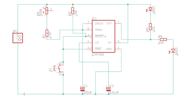
Gambar 1. Schematic

Gambar 2. Board
Untuk lebih jelasnya, layout Schematic dan Board dapat diunduh melalui link di bawah ini :
Langkah 3 : Simulasi

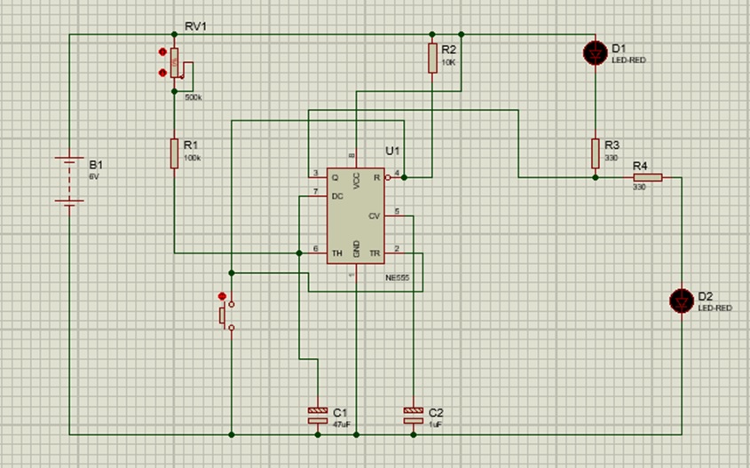
Gambar 3. Proteus
Untuk meminimalisir terjadinya kegagalan dalam pembuatan rangkaian, maka sebelum mencetak PCB rangkaian, terlebih dahulu mensimulasikan rangkaian tersebut pada software Proteus untuk memastikan bahwa output rangkaian yang dibuat dapat berfungsi dengan baik atau tidak.
Hi, today I want to show you about my project using IC NE555. MY project is 5 second delayed LED light. In this project I using the NE555 as an timer IC. But before we go to the next step, in here I want to explain little bit about IC NE555.
What is NE555?
NE555 is one of the most common chip that used in timer circuits. IC NE55 is an 8-pin chip with 2 inputs and an output. So basically IC NE555 can be used in lot of circuits. n most cases you add a capacitor and resistor to produce a circuit known as a TIME DELAY CIRCUIT and the chip has a detection-pin and an amplifier (also called a power amplifier) to product an output.
Light dimmer merupakan sebuah rangkaian yang digunakan sebagai pengatur nilai suplai daya ke lampu. Dengan daya yang dibatasi, maka lampu akan menjadi redup. Begitu juga sebaliknya, ketika daya tidak dibatasi, lampu akan menjadi terang kembali. Umumnya rangkaian ini di pasang pada lampu-lampu yang berada di bioskop, ruang pertemuan, panggung, maupun hotel.
Rangkaian light dimmer yang akan di buat kali ini akan menggunakan komponen-komponen sederhana yang mudah untuk didapatkan. Berikut komponen dan alat yang akan digunakan dalam rangkaian ini.
1. PCB.
2. IC NE555 + Socket 8 pin.
3. Resistor 1KΩ dan 390Ω.
4. Kapasitor nonpolar 100uF (miler).
5. Dioda 1N4148.
6. Potensiometer 50KΩ.
7. Switch.
8. Pin Header.
9. LED.
10. Solder.
11. Timah.
12. Power Supply / Baterai.
13. Gerinda.
14. Multimeter.
15. Osiloskop.
Oke, disini saya akan membahas tentang project yang saya telah kerjakan, yaitu membuat PCB (Printed Circuit Board) Rangkaian Servo Controller menggunakan IC NE555 sebagai pengatur lebar pulsa PWM motor servo. Sebelumnya, saya akan membahas sedikit tentang apa itu IC NE555, dan juga apa itu motor servo.
- IC NE555
IC timer 555 merupakan IC atau sirkuit terpadu (chip) yang digunakan dalam berbagai aplikasi pewaktuan, sumber pulsa gelombang, serta aplikasi osilator. IC ini dapat dimanfaatkan dalam rangkaian elektronika sebagai penunda waktu (Delay Timer).. Secara fisik IC NE555 berbentuk DIP (Dual Inline Package) dengan kaki berjumlah 8 pin.


Recent Comments